S.Carnot a french engineer working in french army. In 1824, he observed that the maximum transformation of heat into work can be possible if all the intermidiate steps in the cyclic processses are carried out reversibly. such reversible cycle is called a CARNOT CYCLE. and the engines operating on the basis of carnot cycle called CARNOT ENGINE.
▪️Although the concept of carnot cycle is totally imaginary and theoretical and cannot be achieved in actual practice, but still the concept of carnot cycle is helpful in the calculation of efficiency of the heat engine.
▪️For understanding the concept of Carnot cycle, i’m showing you an expression for the efficiency of a Carnot engine, using a very systematic arrangement.
▪️let us take a cylinder of any material as the working material and an ideal gas, i.e. , for making the analysis easier and simplified. So for the deriving of efficiency of a carnot engine.
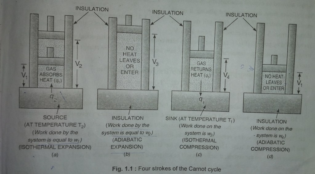
▪️Carnot took one mole of an ideal gas as the working substance in a cylinder fitted with a weightless and frictionless piston so that all the process can be carried out reversibly. and, The cylinder is supposed to be insulated from all the sides except from the bottom, which allows the flow of heat to or from the system through the bottom only. The cylinder can be placed on two reservoirs, one at a higher temperature T₂, called SOURCE, and the other at lower temperature T₁, called SINK.
▪️If the process is carried out by placing the cylinder on the source or sink, it can continously exchange the heat with surroundings resulting in the decreasing or increasing the temperature, so that the temperature remains constant. such processes are called ISOTHERMAL – PROCESSES. while ,
▪️If the process is carried out by placing the cylinder on an isulating material, then, no exchnage of heat take place with surroundings, such processes are called ADIABATIC PROCESSES.
STEPS INCLUDING CARNOT CYCLE.
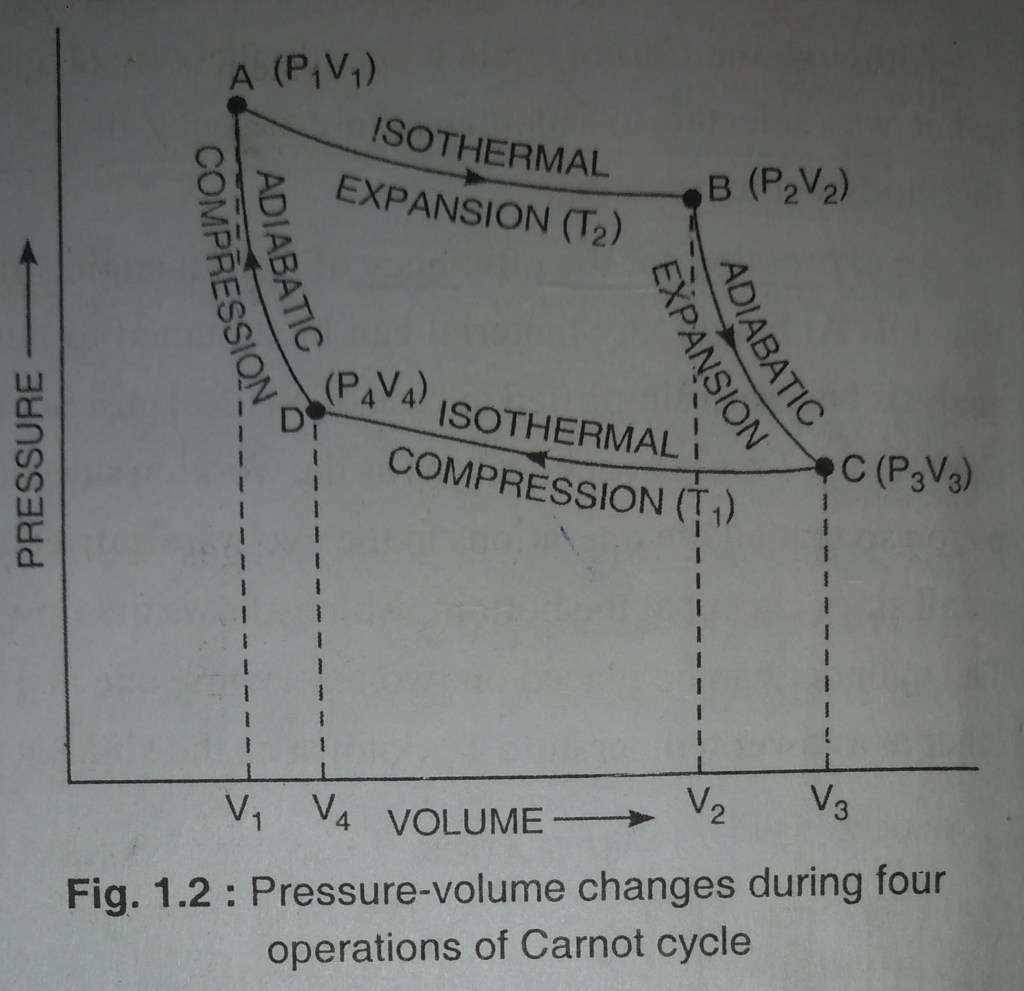
Carnot cycle complete in the following four steps. the value of pressure – volume changes during these steps. as shown in Fig.1.2
I. STEP – 1. Isothermal Expansion :
The cylinder containing one mole of an ideal gas is allowed to expand isothermally and reversibly by placing the cylinder on the source of temperature T₂,[Fig. 1.1 (a)] till its volume increases from V₁ to V₂ represnted by the point A to B Fig. 1.2 . The change in volume is reprsented by curve AB
Since in the isothermal expansion of an ideal gas, ΔE = 0, it follows the first law of thermodynamics ” heat absorbed is equal to the work done by the system on the surroundings. If q₂is the amount of heat absorbed by the system at temperatute T₂, and w₁ is the work done by the system on surroundings, then
q₂ = – w₁ = RT₂ ln V₂/V₁ … (i)
( since q₂ is the amount of heat absorbed by the system and w₁ is the amount of work done by the system on the surroundings .∴ according to the sign conventions, q₂ has been taken positive and w₁ has been negative.)
II. STEP – 2 Adiabatic Expansion :
The gas now allowed to expand adiabatically by removing the cylinder from the source and place it on an insulating material [Fig. 1.1 (b) ] until its volume changes from V₂ to V₃ represented by point B and point C respectively. shown in (Fig. 1.2. Since work has been done by the system adiabatically and no heat enters or leaves the system, then, the temperature of the system falls from T₂ to T₁, this change is represented by the curve BC.
let the work done during this adiabatic expansion is represented by w₂. then
– w₂ = Cᵥ (T₁ – T₂)
= – Cᵥ( T₂-T₁). … (ii)
where, Cᵥ is the heat capacity of the ideal gas, And w₂ is work done by the system hence, taken as negative.
III. STEP – 3. Isothermal Compression:
Now, in this step, place the cylinder on the sink having temperature T₁. by doing this the ideal gas is compressed reversibly and isothermally at temperature T₁, so the volume of gas is decreased from V₃ to V₄ represented by point C and D repectively.[Fig. 1.1 (c)]. The whole process is represented by the curve CD. ( Fig. 1.2).
in this step, work is done on the system. hence taken as positive and, given by,
w₃ = RT₁ ln V₄ / V₃ … (iii)
q₁ is the amount of heat transfered to the surrounding by the system at temperature T₁, hence taken as negative. then q₁ is equal to the w₃, expression is given by
w₃ = RT₁ ln V₄/V₃ … (iv)
IV. STEP – 4. Adiabatic Compression :
The cylinder is now removed from the sink and placed again on an insulating material [Fig. 1.1 (d)].
Now the gas is compressed adiabatically and reversibly until is attains its original volume V₁1 and temperature T₂. the whole process is represented by the curve DA (Fig. 1.2).
▪️In this step, work is done on the system ∴ work taken as positive and is given by.
w₄= Cᵥ (T₂ – T₁) … (v)
The net work is done by the system in the whole cycle is given by
w = (-w₁) + (-w₂) + w₃+ w₄
= RT₂ ln V₂/V₁ – Cᵥ(T₂-T₁) + RT₁ ln V₄/V₃ + Cᵥ(T₂ – T₁)
= RT₂ ln V₂/V₁ + RT₁ ln V₄/V₃ … (vi)
- For adiabatic expression of the ideal gas during steps 2 and 4, we can write,
Cᵥ ln T₂/T₁ = R ln V₃/V₂ … (vii)
Cᵥ ln T₂/T₁ = R ln V₄/V₁ … (viii)
from equations (vii) and (viii), we have
V₃/V₄ = V₄/V₁ or V₄/V₃ = V₁/V₂ … (ix)
Putting the value of V₄/V₃ in equation (vi), net work done ![]() is given by
is given by
w = RT₂ ln V₂/V₁ + RT₁ ln V₁/V₂ = RT₂ ln V₂/V₁ – RT₁ ln V₂/V₁.
w = R(T₂-T₁) ln V₂/V₁ … (x)
Net heat absorbed by the system
The net heat absorbed (q), by the system in the whole process is given by.
q = q₂ + (-q₁) = RT₂ ln V₂/V₁ + RT₁ ln V₄/V₃
= RT₂ ln V₂/V₁ – RT₁ ln V₁/V₂ {∵ V₄/V₃ = V₁/V₂…..from eq. (ix)}
RT₂ ln V₂/V₁- RT₁ ln V₂/V₁
q = R (T₂ – T₁) ln V₂/V₁ … (xi)
It can be concluded from equation (x) and(xi) that
q = w
Thus, the essential condition for a cyclic process that net work done is equal to net amount of heat absorbed is full-filled.